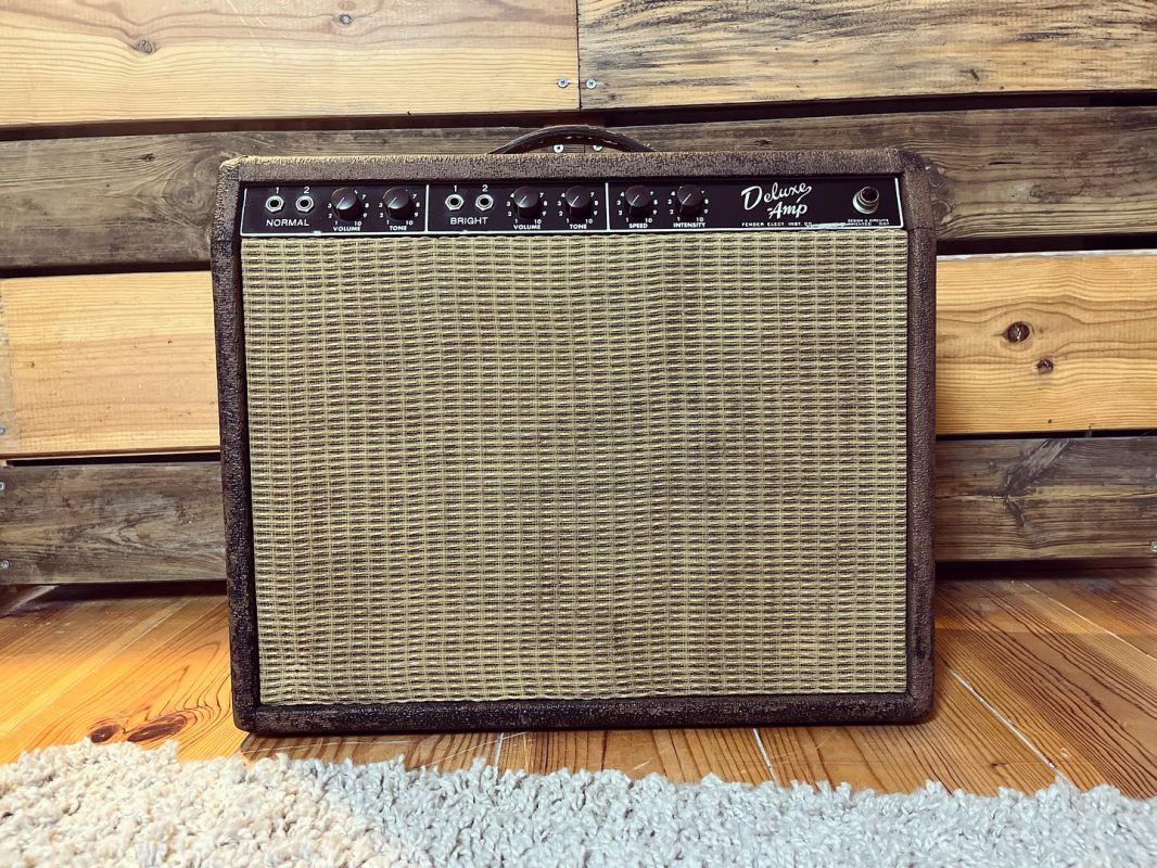
This amp gets the TLC it needs to become safe and sound again, ready for a next life in music!
Where we stand
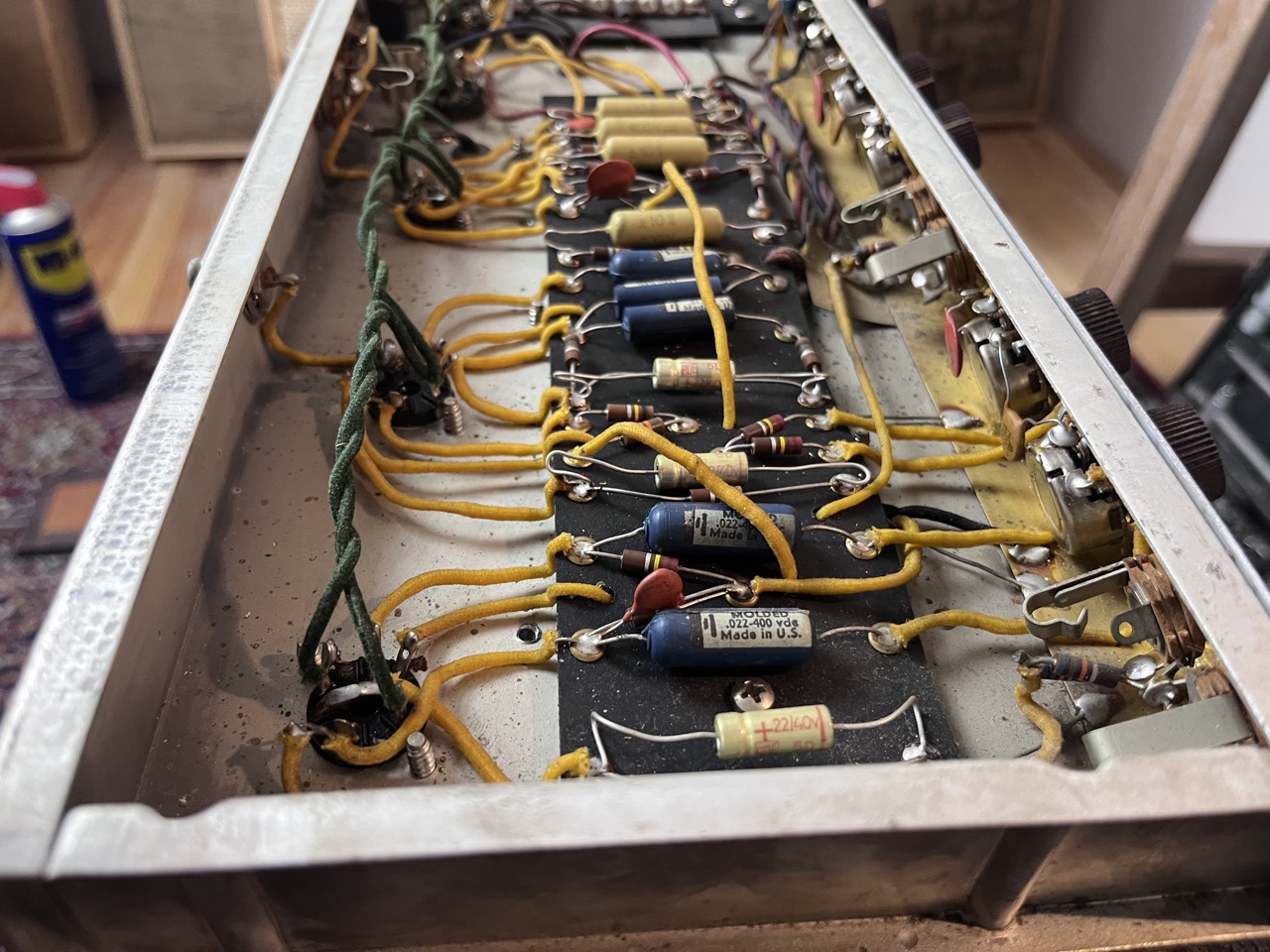
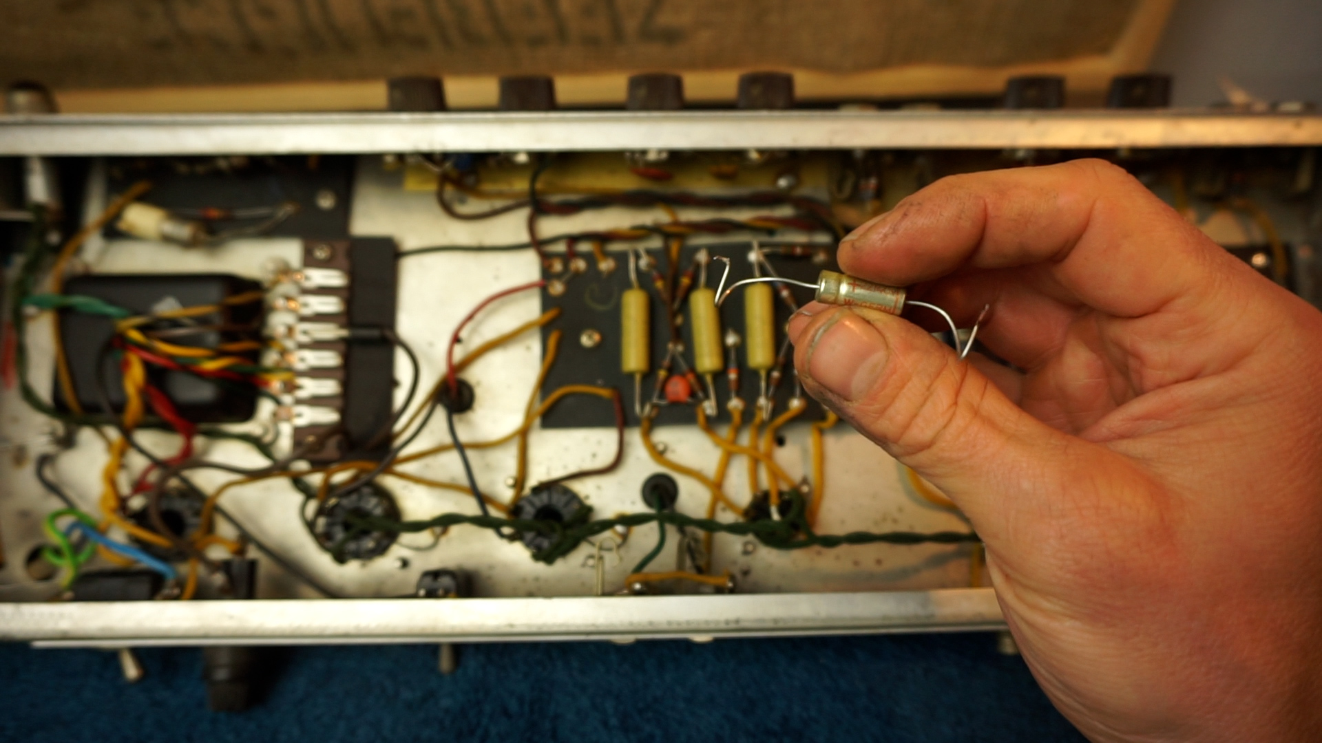
So, when I pulled the chassis out of the cabinet I was pleasant surprised. Most of the original Ajax blue molded caps are there. I think all of the resistors are original, or at least replaced with the carbon comp resistors that are typical for this era. There’s a few mustard caps in the phase inverter circuit, but I’m not too worried about that. In the future, hunting down original NOS blue molded ones would be nice, though. Maybe these mustard are about equal in value. 😉
The circuitboard has been recapped somewhere in the 1970s I suppose so they are not optimal for use at this point, though they still function.
Circuitboard
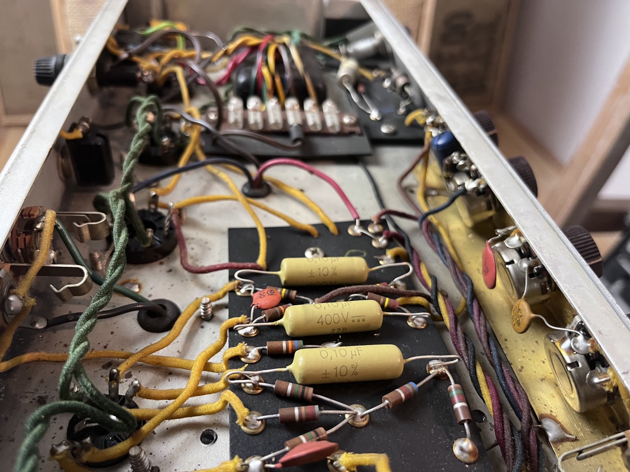
Mustard Caps
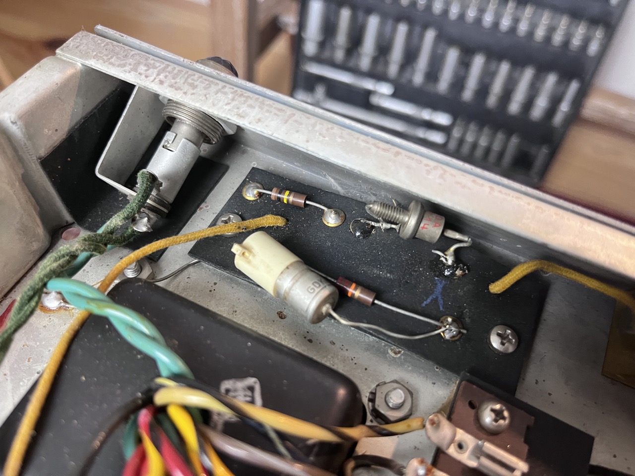
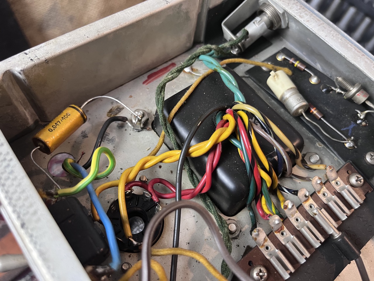
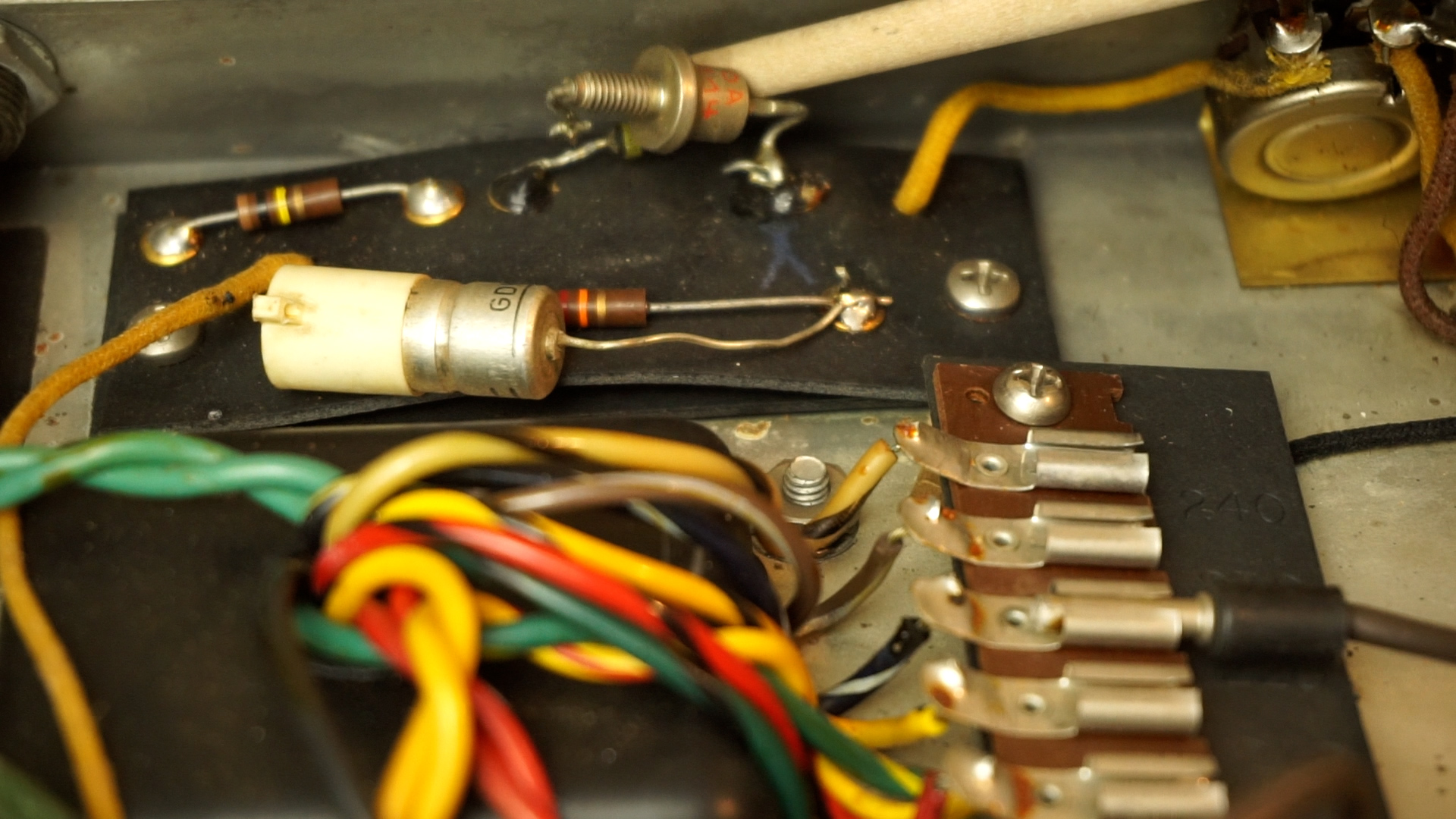
The bias section has a weird new capacitor and a new diode that looks more like a car part then fine electronics. The original diode was also still under there too, but clipped off. Very messy.
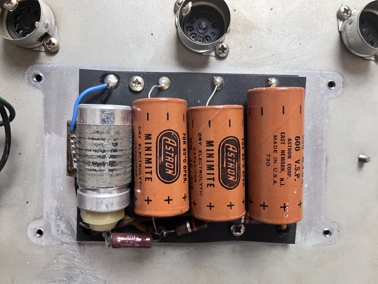
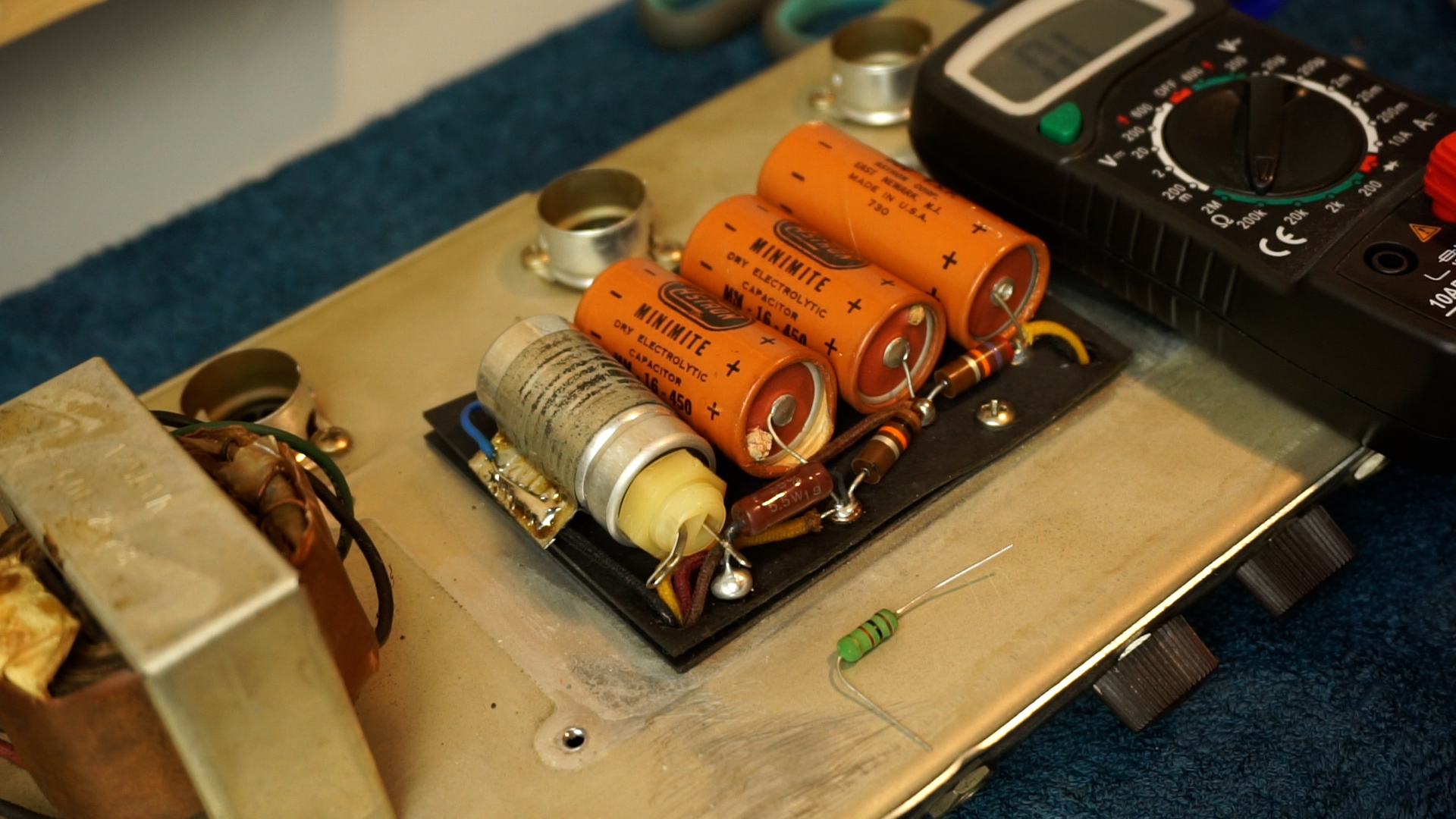
Under the doghouse cover we find 3 original Astrons and 1 pretty weird what seems to be industrial style of capacitor. The 1K dropping resistor has been replaced with a 5.5w one. We’ll measure it and see if we replace any of these. They are critical, but usually they handle time ok!
Bias Section
Filter Capacitors
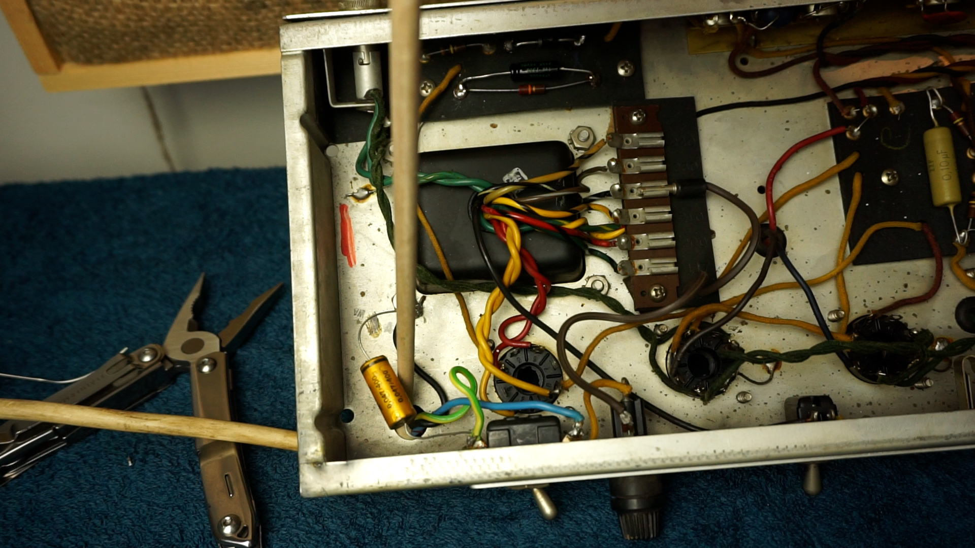
The power chord connects to the death cap circuitry, and it’s all very poorly done so we need to obviously correct that, but of course this amp gets a 21st century ground system.
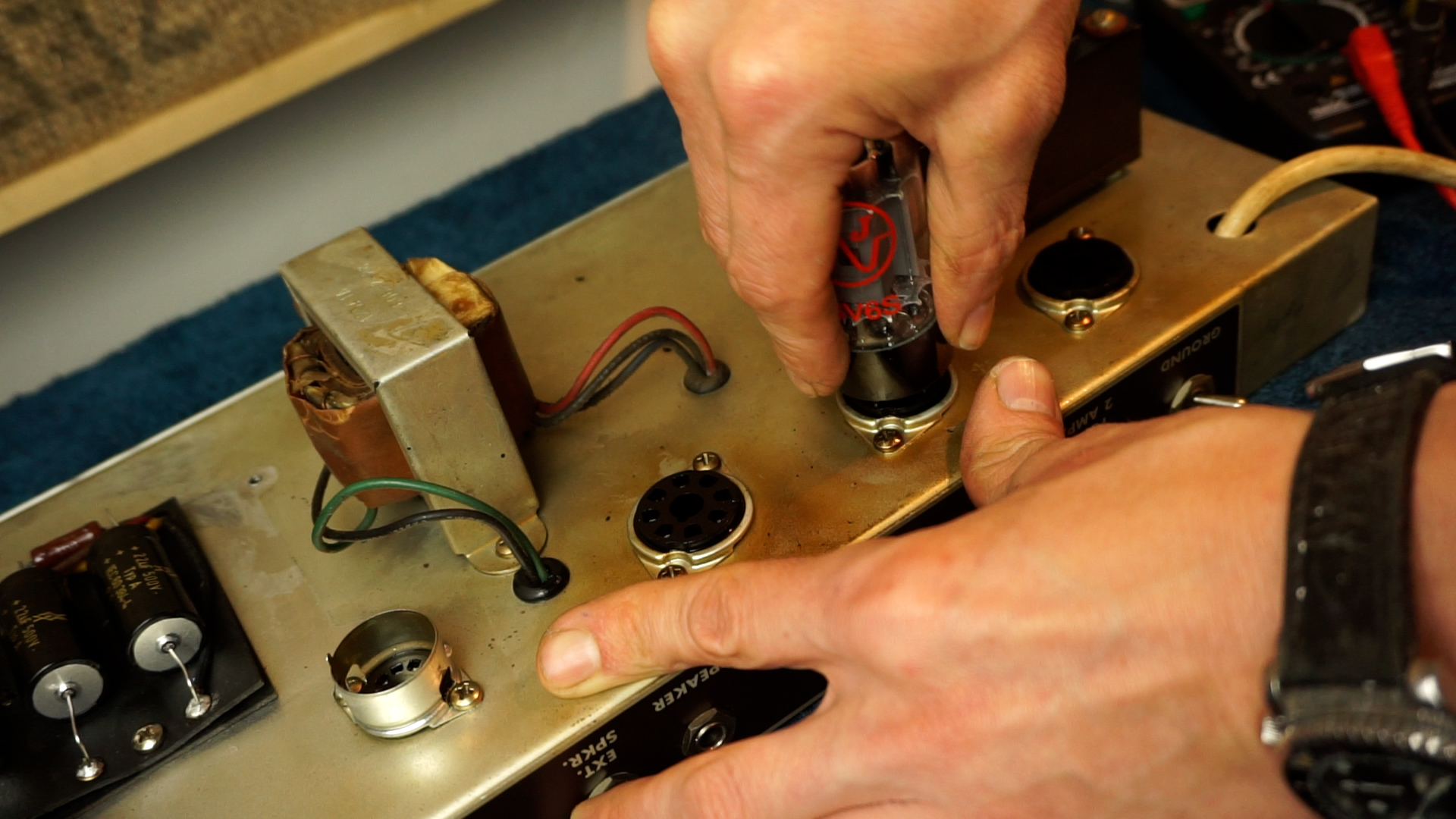
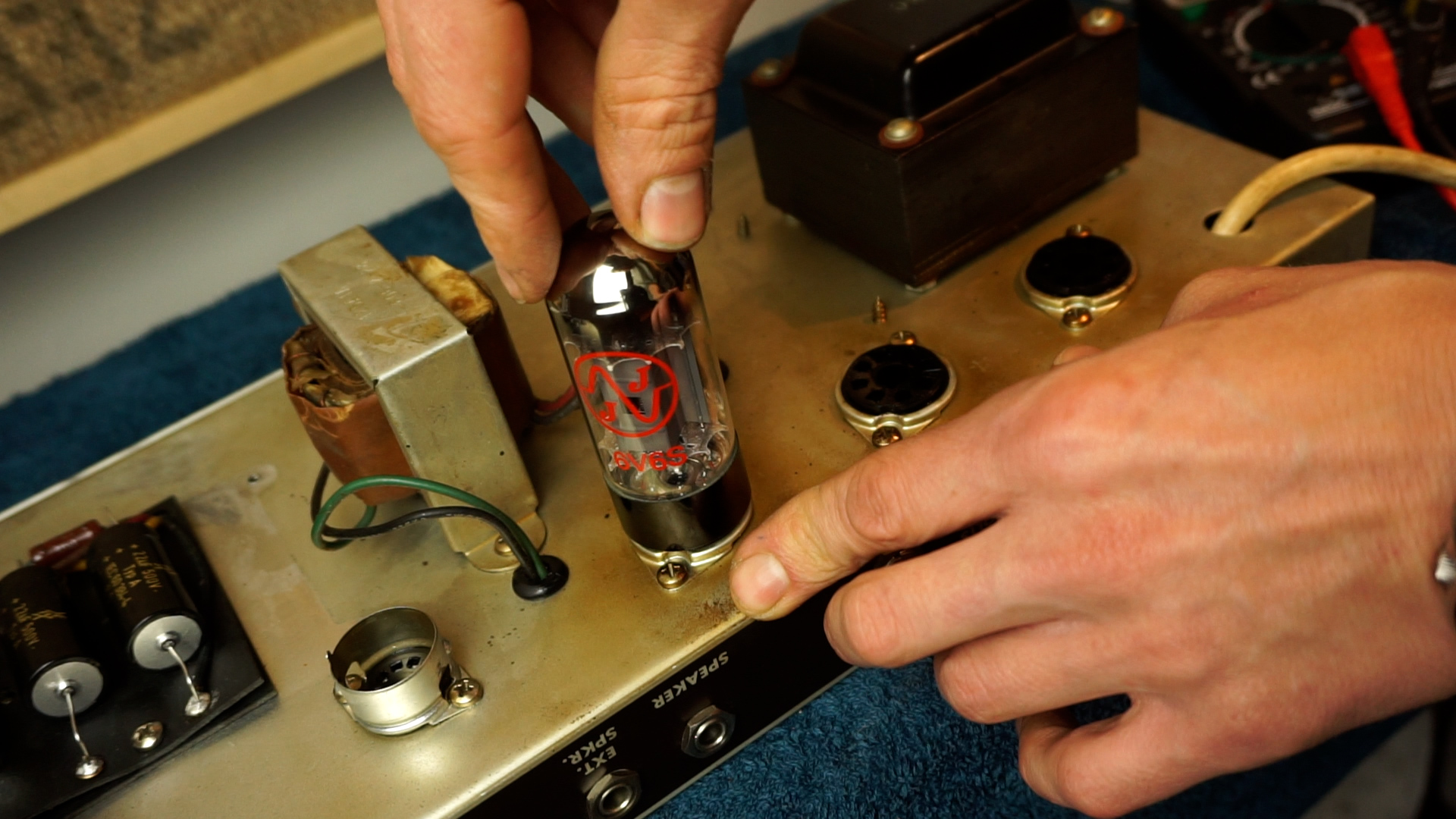
The tube sockets, pots and jack inputs need a good cleaning. The 6v6’s are a little bit rocky, so we need to see if we can tighten the pins as we want to keep things as original as possible.
Death Cap Circuity
Tube Sockets
Replacing The Electrolytics
The electrolytics that are on the circuitboard are better described as cathode bypass capacitors based on what their function is. Out came 25uF@50v’s, in go Sprague 25uF@25v.
Old Cathode Bypass Capacitors
New Sprague Atom Capacitors
Bias Section Work
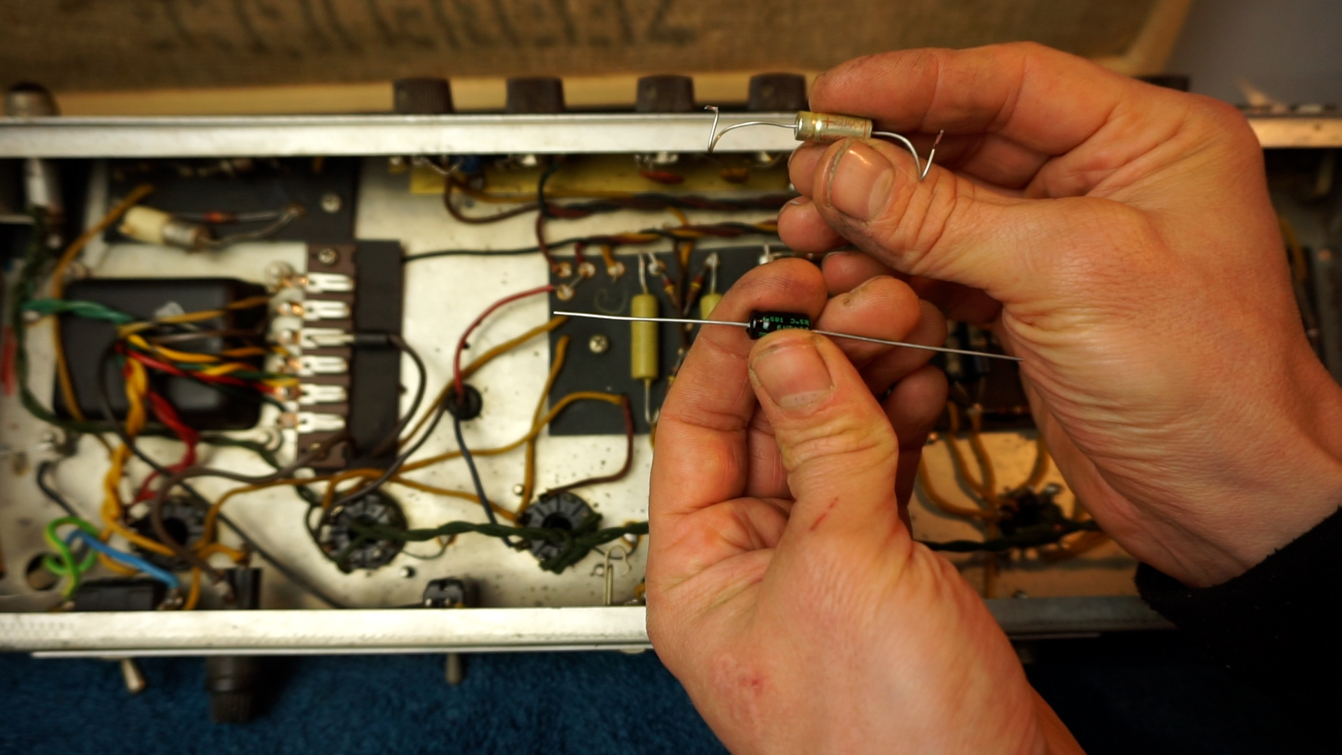
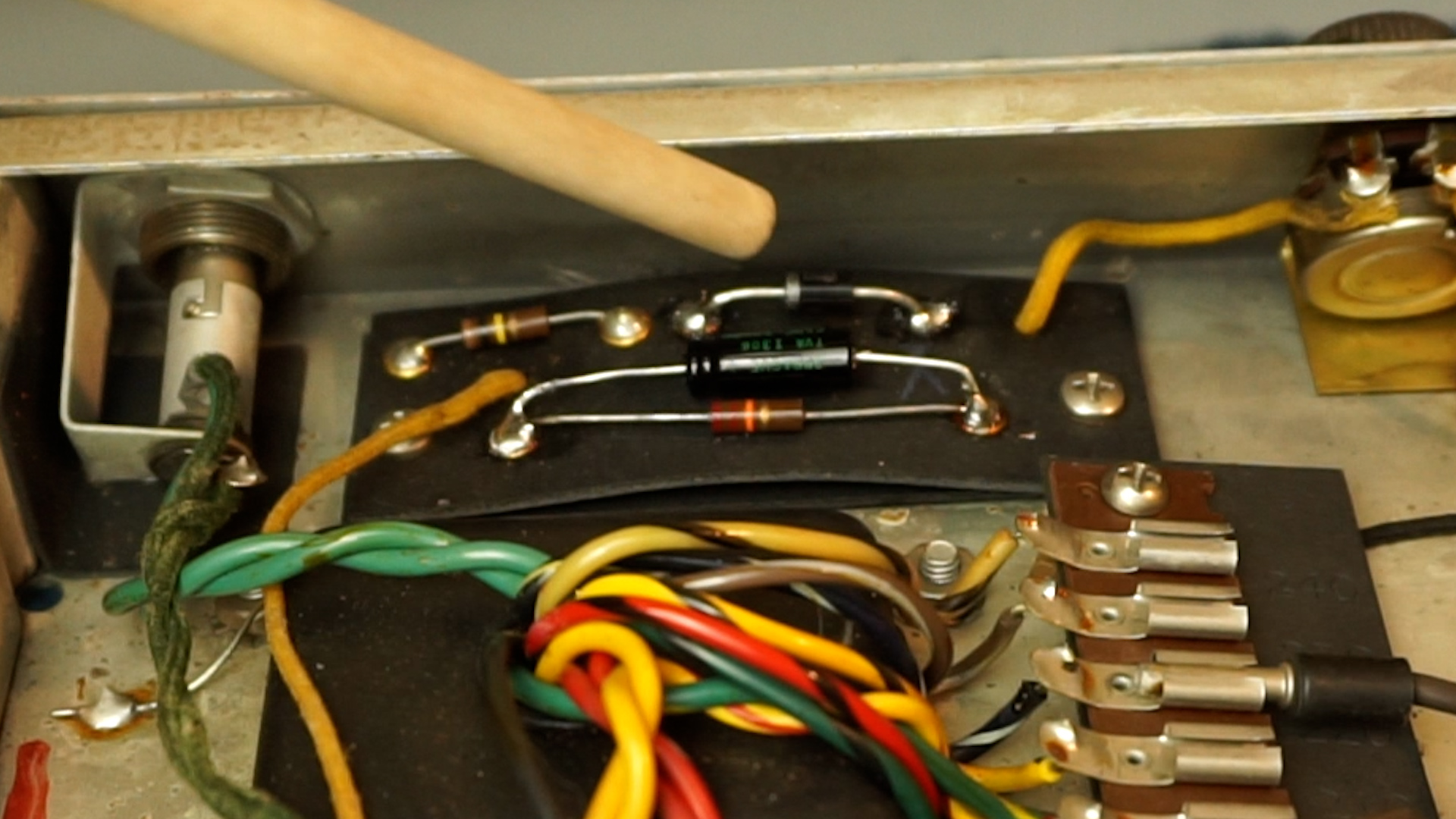
So yeah that weird cap and diode. The diode wasn’t even really well connected, all pretty dangerous to operate, so I’m a bit sorry that I gave the amp even a test when I got it. For a diode we go for a well sized 1N1007, and a Sprague 25uF@50v goes in there. It’s kind of a shame that the work that was done in the past involved using these goofy parts while good original components were still available. But they probably functioned just the same of course.
Bias Section with replacement parts
Bias section with correct parts
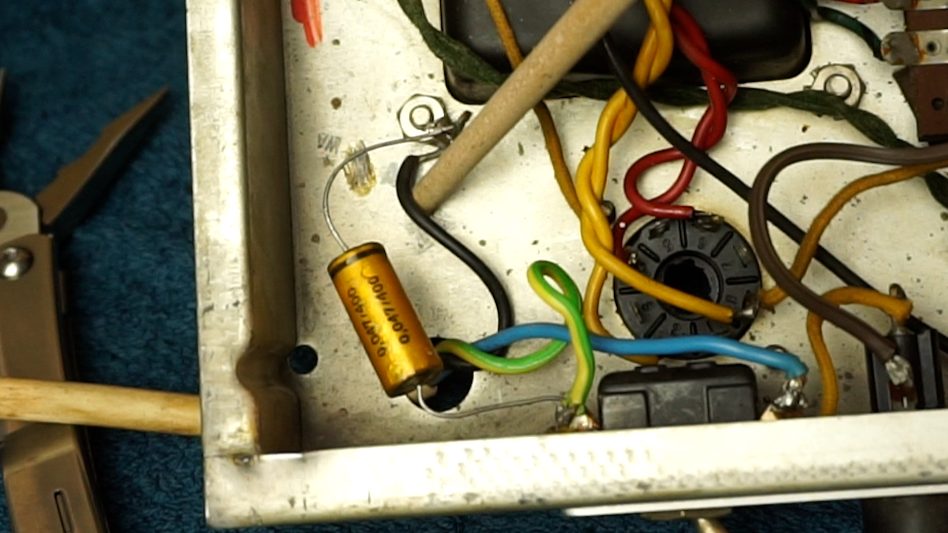
The Infamous Death Cap Circuitry
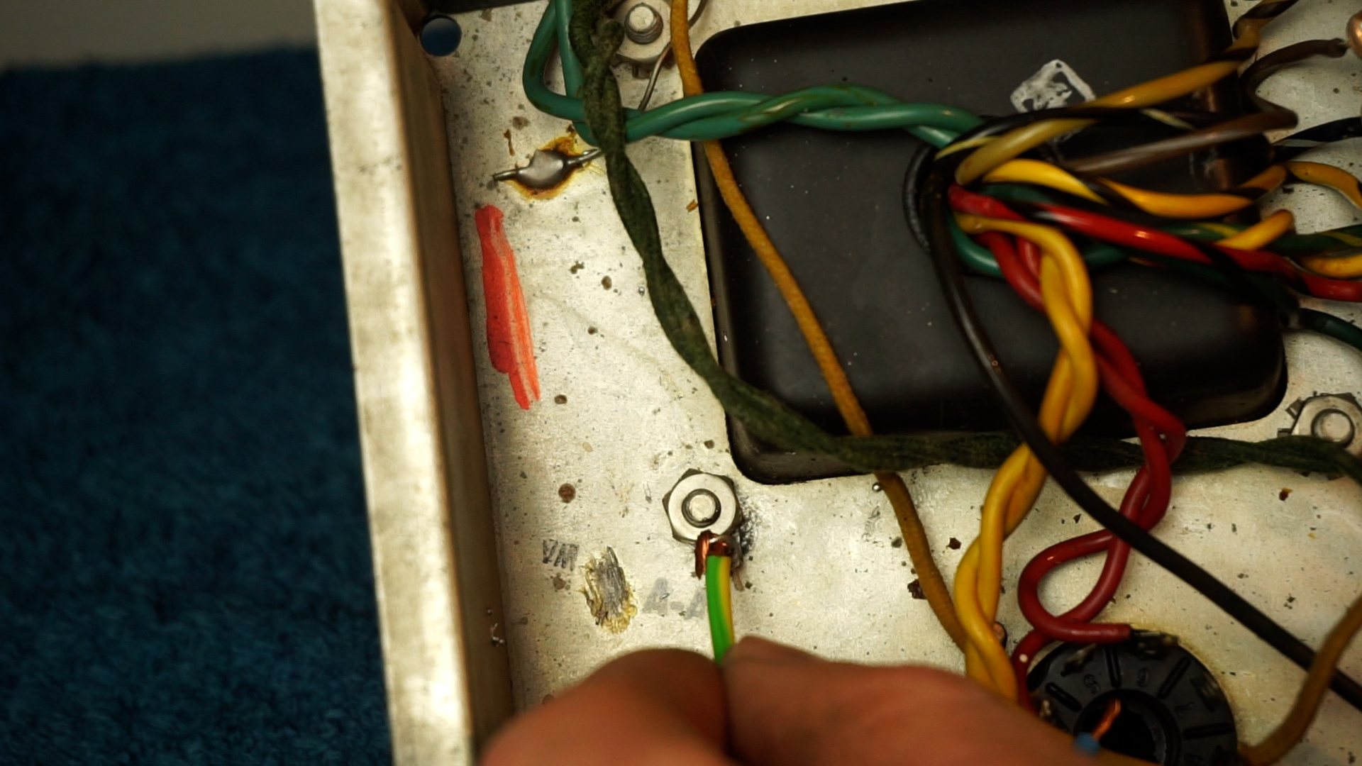
For those who know the basics of electronics, just looking at it is already striking. One lead of our power chord gets connected to the chassis…oof…and in this amp the power chord was also poorly attached so we had a hot lead loosely connected even.
In theory we are protect by the ‘death’ capacitors that’s going to block our voltage in one direction, but once that fails, that’s our ass if there’s no ground going back into the wall. In case of an original 2 prong Lifting the ground to reduce hum is therefor pretty dangerous, but also in a 3 prong situation the risk of becoming a ground touching a hot lead or hot chassis is just out of this world. Out it all goes, but I’ve left the ground switch to provide a terminal to leave as much original yellow cloth wire in place.
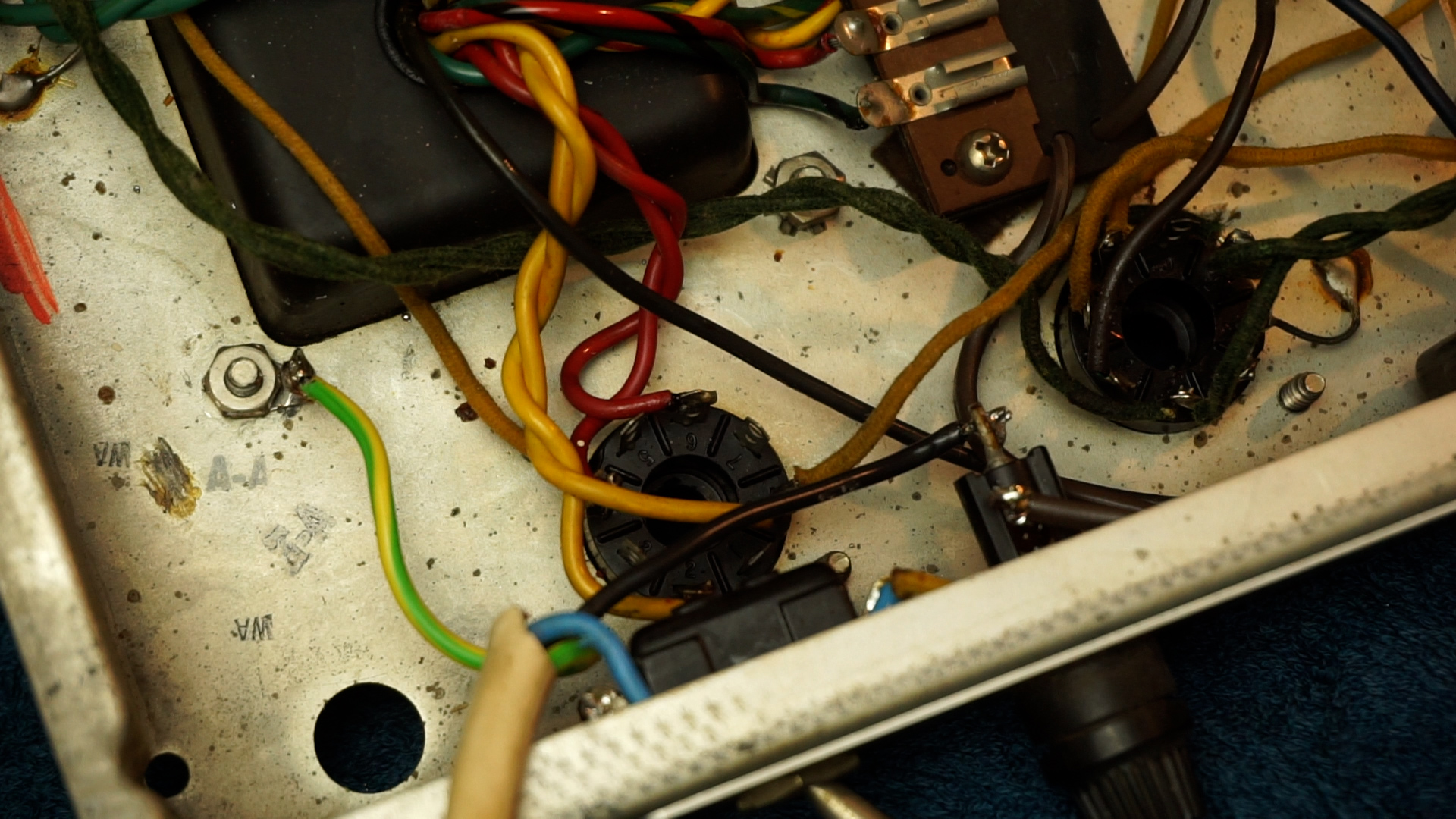
Lethal Shit
Floating Power Connection
Ground goes to chassis, with a strong mechanical connection to begin with. One end of our hot or cold, depending on which way you’re plugged in goes to the switch that switched to one end of our power transformer, and the other end to the fuse which goes to the other end of the power transformer. As logical as that seems today, many vintage amps aren’t wired like this yet so beware.
Solid Mechanical Connection
Modern Power Cable Wiring
Filter Capacitors
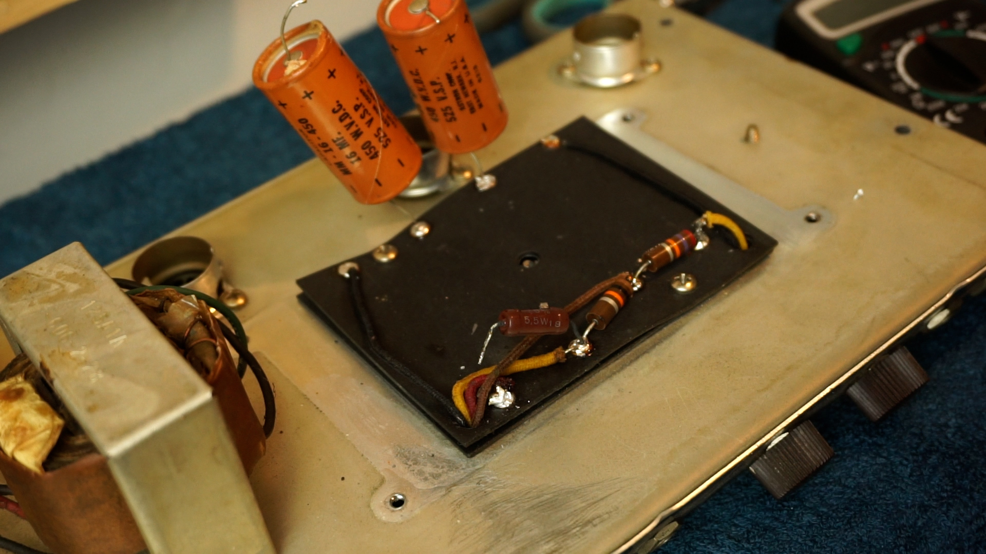
The original Astrons at this point in time are well expired. The 8uF seems allright still from a visual perspective. The other 2 16uF’s are showing leaking electrolyte. The industrial looking replacement is probably still functioning. However, it’s time for a proper update of course.
All of the dropping resistors measure out good, so we leave them in place, but tidy things up a bit.
Vintage Astron Filter Capacitors
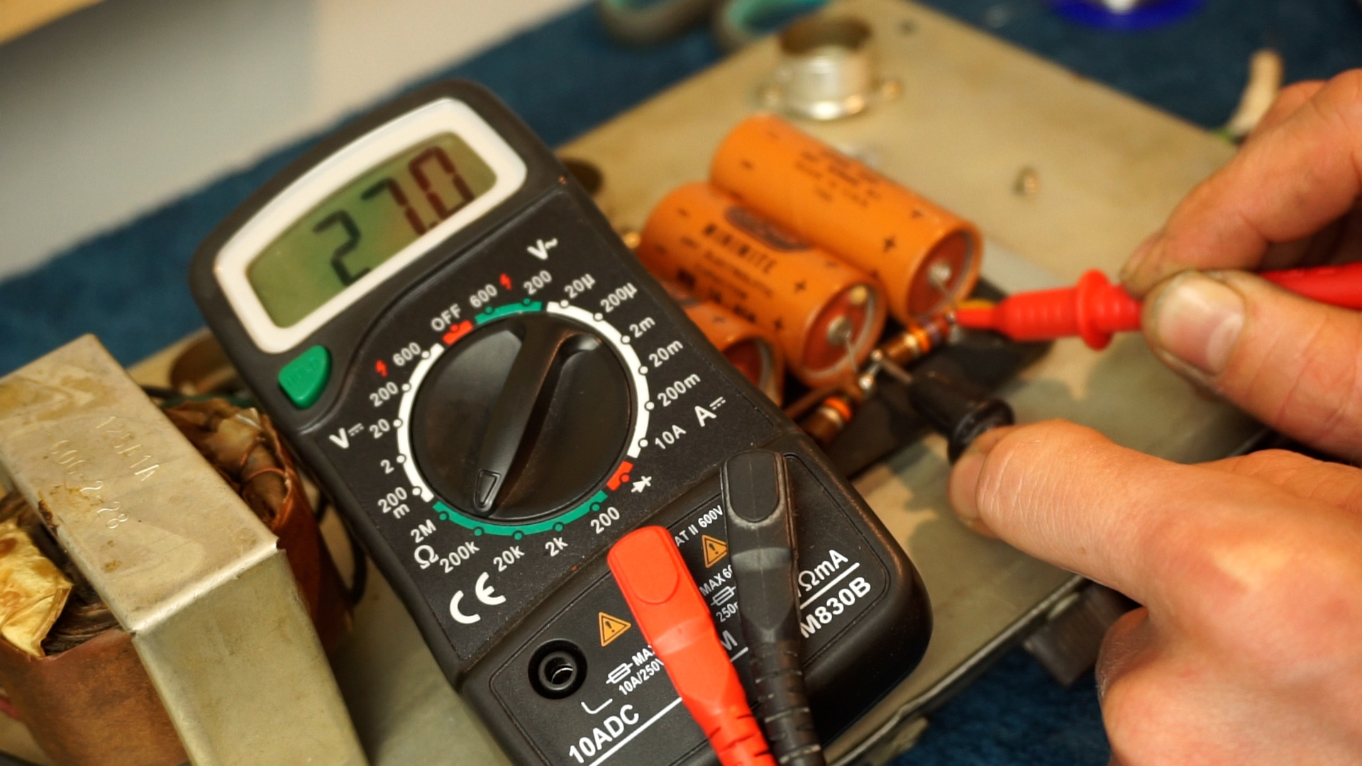
Measuring Voltage Dropping Resistors
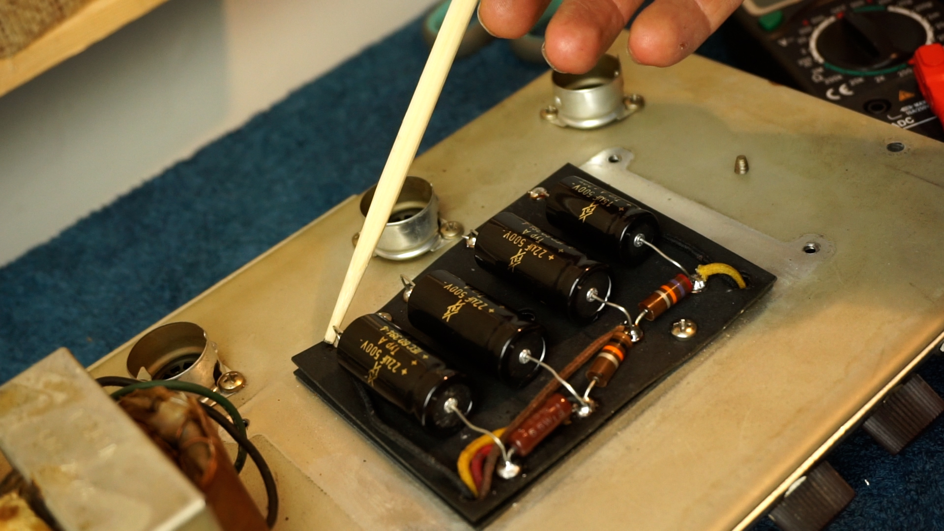
Now, availability is thing. For F&T, the best could come up with was 22/22/22/10. Upping these in value isn’t such a bad plan and maybe the main filter cap gets an even higher value in the future to provide a little more current ripple filtering, or as you may want to refer to as hum cancelling.
Replacing Filter Caps
New Filter Cap Section
Tube Sockets, Pots & Jack Inputs
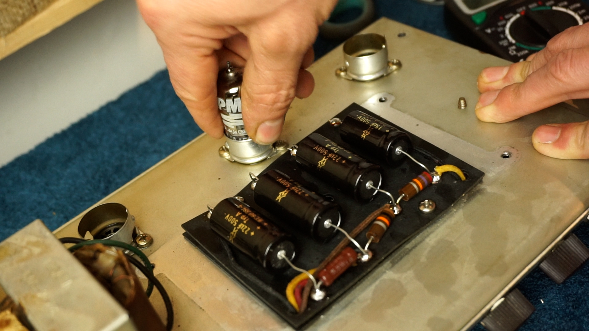
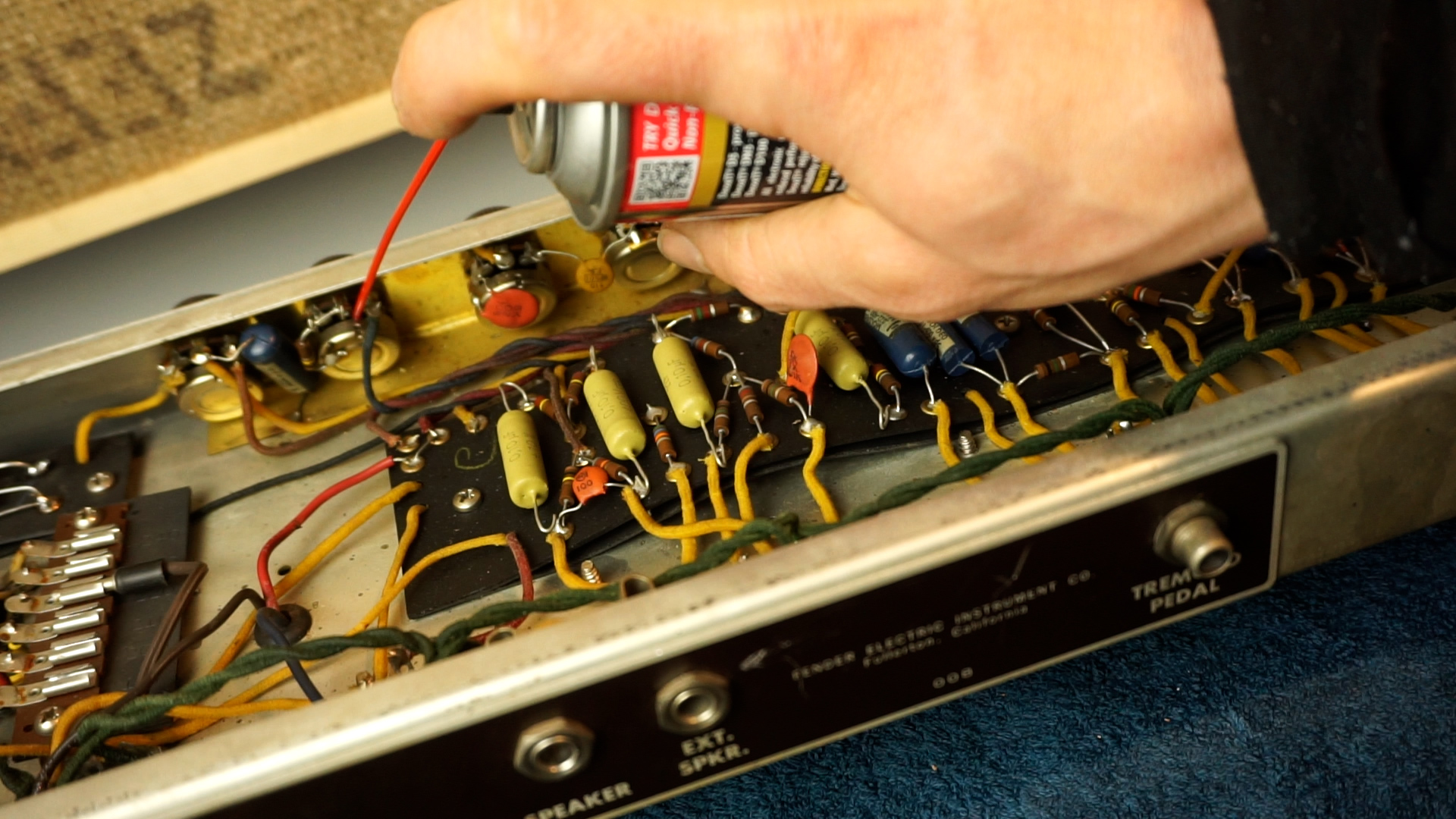
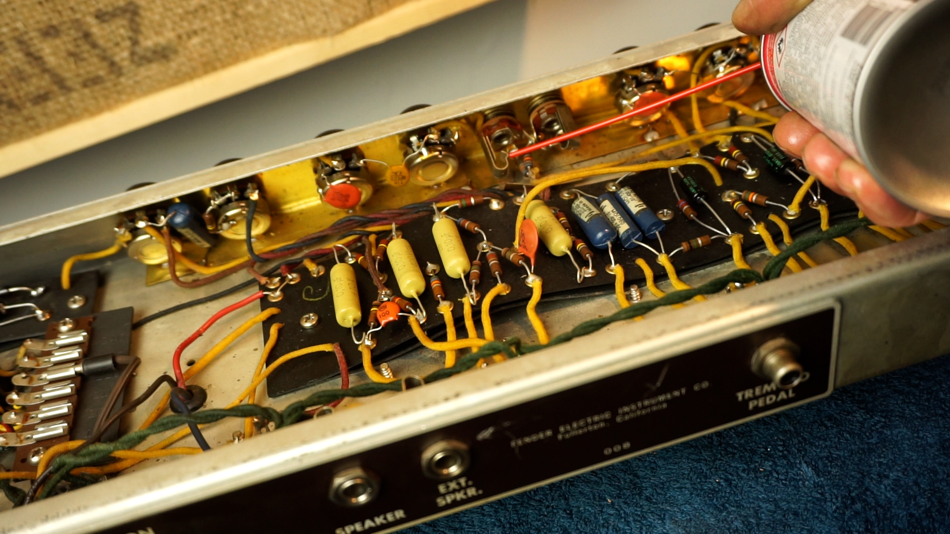
Cleaning tube sockets is a pretty fun process. You spray them with some De-Oxit, wonderful stuff. Then we insert and pull out a tube. You also clean the terminals of the tube that way. Well, I didn’t use those nice vintage tubes that came out of the amp, but used something non critical for this.
Spraying Tube Sockets
Cleaning Tubesockets with Tubes
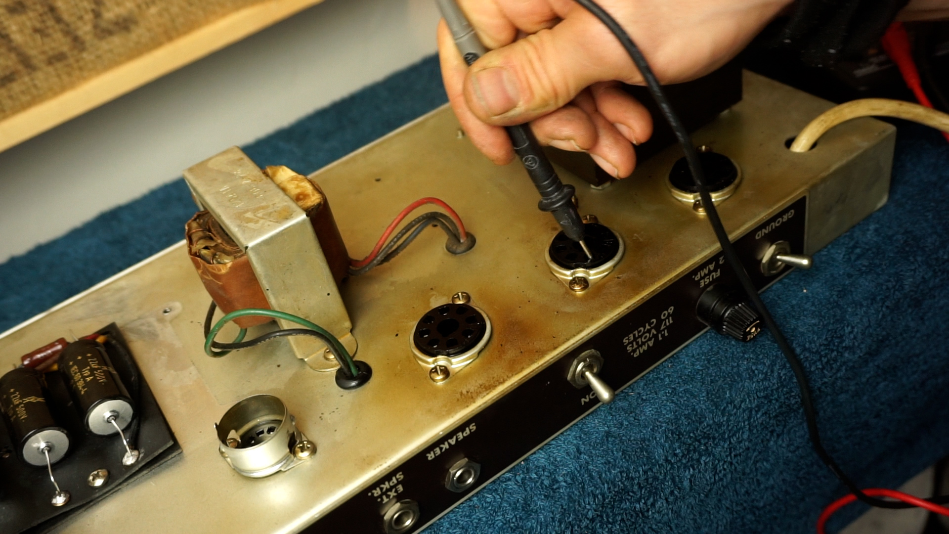
Now, the 6v6 power tubes showed a little rocky-ness so after cleaning I’ve tried tightening the pins with one end of a multimeter probe. Not perfectly tight, but it did improve somewhat. The rectifier was still very solid.
Power Tube Sockets
Tightening The Pins
You spray into the pot and turn the knobs back and forth a couple of times. After drying up of the fluid, repeat the process. For the jack inputs you can use a pipe cleaner or a jack cable, or plug.
Spraying Potmeters
Spraying Jack Inputs
Recap
So, that’s hopefully all we have to do to make it safe and sound again! On the right, you’ll this whole process in more detail in a video.
In the next part we will plug it into a speaker, do a fire-test and soundcheck. We then check on the bias because with today’s level of wall voltage we might need to arrange a few things for an optimal performance and durability.